
The strength within.
A complete X-ray of the wall, floor and foundation. One system, before a single layer moves.
03 / Construction technology
See through it.
Understand how it comes together.
Start with a complete X-ray, open the wall and floor layers, discover their materials, then watch the assembly come back together. One continuous view of the technology, from the inside out.
Explore the assembly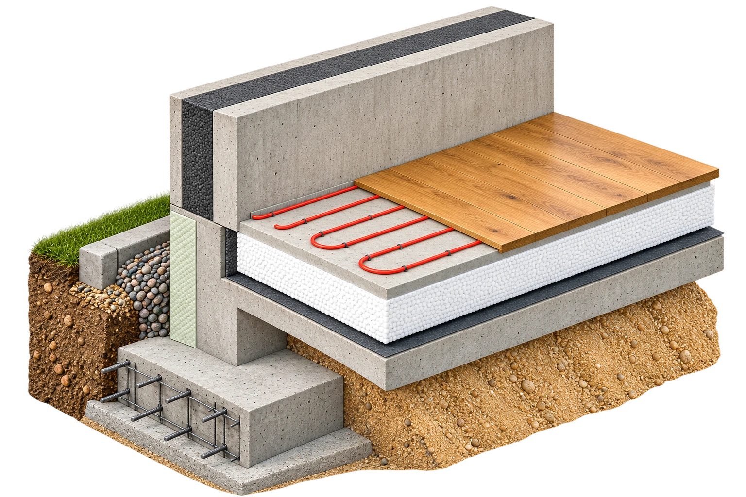
Concrete. From the inside out.
A complete X-ray of the wall, floor and foundation. One system, before a single layer moves.
The assembly opens. Concrete, insulation and structural support each reveal their place in the whole.
Concrete for structure. Insulation around the envelope. Heating and timber where the building becomes a place to live.
The components return to the same coordinated assembly. Every connection, considered together.
From the structure to the finishing layers. One complete reference assembly, made tangible.
Scroll to discover
Illustrative reference. Project-specific engineering and approvals.
Explore the specificationsPreparing the construction assembly…
The X-ray shows an illustrative internal reinforcement cage with concrete cover and support blocks. It does not specify anchor bolts or structural connections. The visual explains how the reference components connect. Nominal layer dimensions and wall options are set out in the technical reference; the approved design determines the specification for each project.
The reference build-up
The cutaway shows one coordinated construction assembly, from the concrete facade to the prepared ground. These are reference details for discussion, not a specification for every site.
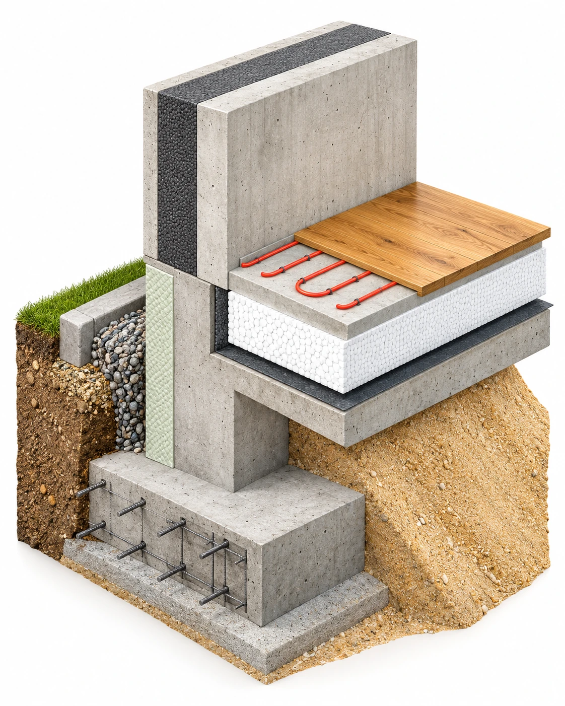
| Key | Layer or component | Reference |
|---|---|---|
| 01 | Concrete facade | 6 cm |
| 02 | Graphite EPS 031 wall insulation | 18 cm |
| 03 | Structural concrete wall | 14 cm |
| 04 | Floor finish | As specified |
| 05 | Underfloor heating | Within screed |
| 06 | Cement screed | 6 cm |
| 07 | EPS 100 floor insulation | 20 cm |
| 08 | Separation membrane | As specified |
| 09 | Concrete sub-base | 10 cm |
| 10 | Compacted sand fill | 50 cm |
| 11 | Concrete foundation stem | Project-specific |
| 12 | Moisture-resistant perimeter insulation | Project-specific |
| 13 | Gravel border and concrete kerb | As specified |
| 14 | Reinforced concrete strip footing | 30 × 60 cm |
| 15 | Lean concrete blinding | 10 cm |
Foundation dimensions, drainage, moisture protection and insulation are designed for the ground conditions, climate and local requirements. The model homes will use the specification selected and approved for that project.
A system that fits the brief
Concrete on both sides. Space for services. Or a rendered exterior. Follow the layers at full scale and see how each reference assembly is built.
Enter the wall sequence01 / Concrete sandwich
A structural concrete inner leaf and a concrete facade, with graphite insulation held between them. A substantial wall with an integrated exterior finish.
02 / Interior service cavity
Concrete outside, insulation inside, then timber battens, a vapor-control layer and plasterboard. A coordinated space for interior services.
03 / Rendered exterior
A structural concrete leaf with graphite insulation on the exterior and a thin rendered finish. The external expression changes; the structural role stays clear.
Scroll to reveal
Illustrative sections. Thin finishes and membranes enlarged for visibility.
Compare the specificationsConcrete. Both sides.
Keep the complete reference in view. These are nominal assembly values; the final design determines the wall, openings, connections and performance requirements.
| Assembly | Reference build-up, outside to inside | Nominal thickness | Reference U-value |
|---|---|---|---|
| Concrete sandwich | 6 cm concrete facade · 18 cm graphite EPS 031 · 14 cm structural concrete · interior finish as specified. | 38 cm | 0.164 W/m²K |
| Interior service cavity | 10 cm structural concrete · 5 + 18 cm graphite EPS 031 · 2 cm timber battens · 0.2 mm PE vapor-control film · plasterboard lining. | 36.25 cm | 0.147 W/m²K |
| Rendered exterior | Thin exterior render · 18 cm graphite EPS 031 · 14 cm structural concrete · interior finish as specified. | 32 cm | 0.160 W/m²K |
Thicknesses and thermal transmittance values describe reference assemblies. Lower U-values indicate less heat transfer through the wall. Whole-building energy performance, moisture control, fire and acoustic requirements, structure and local approvals are assessed for the project. The film, finishes, openings and visual separation are illustrative; this sequence is not a dimensioned construction detail.
From the first drawing to the site
Factory production is one part of the delivery. The value comes from coordinating the building, the manufacturing plan and the site as a whole.
Resolve the brief, structure, openings and service routes. Align engineering, dimensions and connection details before production begins.
Manufacture specified concrete and insulation components in controlled factory conditions. Coordinate dimensional checks and delivery sequencing while site preparation progresses.
Confirm foundations, access and lifting plans. Deliver prepared elements for assembly, then coordinate the envelope, services and finishing trades.
Engineering, transport constraints, ground conditions and local rules shape the final system. Scope, responsibilities, specifications and programme are agreed with the relevant specialists before delivery.
Start with your brief
Tell us what you want to build, where it is located and how far the design has progressed.
Discuss your construction briefBefore you build
Explore the questions that connect the site, the scope and the delivery strategy.